Introduction :-
Micro-tunneling (MT) can be described as a remotely controlled, guided pipe jacking process that provides continuous support to the excavation face. MT was developed in 1975 in Japan and introduced in the United States in 1984.
Description :-
MT can be used for installing conduits beneath roadways in a wide range of soil conditions, while maintaining close tolerances to line and grade from the drive shaft to the reception shaft. The MT process is a cyclic pipe jacking process.
There are two types of MT methods: slurry type and auger type. In the slurry type method, slurry is pumped to the face of the MTBM. Excavated materials mixed with slurry are transported to the driving shaft, and discharged at the soil separation unit above the ground. In an auger type method, excavated materials are transported by the auger in the casing, and directly discharged on the ground. The slurry MT system is capable of handling wet, unstable ground conditions. The slurry MT system has five independent systems:
- Micro-tunnel boring machine (MTBM),
- Jacking or propulsion system,
- Spoil Removal system,
- Laser Guidance and Remote Control system, and
- Pipe Lubrication system.
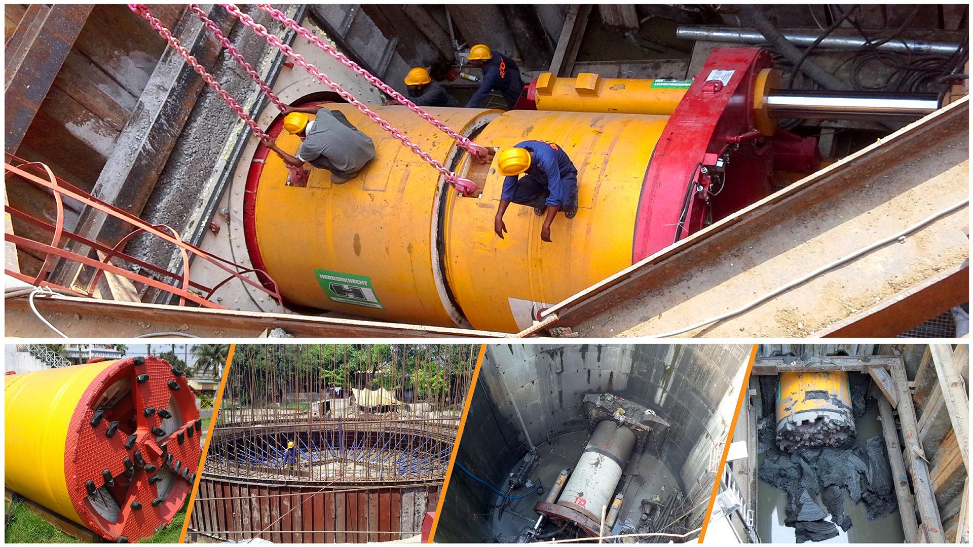
Slurry type MTBM :-
In this method, soil is excavated mechanically by a rotating cutting head. The rotation of the cutting head can be eccentric or centric, and the speed of rotation (RPM) can be constant or variable. Cutter heads are bi-rotational. The head normally rotates in clockwise direction when looking from the rear of the machine. Reverse rotation can provide more flexibility to overcome obstructions and the difficult ground condition. The spoil excavated at the face is extruded through small parts located at the rear of the MTBM face into the mixing chamber. The main functions of this chamber are to mix the spoil with clean water from the separation system and control hydro-static head imposed on the MTBM face by a body of water or groundwater.
Jacking system :-
The jacking system consists of the jacking frame and jacks. The jacking capacity ranges from approximately 100 tons to over 1,000 tons. The jacking capacity is mainly determined by the length and diameter of the bore and the soil. The soil resistances are generated from face pressure, friction, and adhesion along the length of the steering head and pipe string. The jacking system determines two major factors of the MT operation: the total force or hydraulic pressure and the penetration rate of pipe. The total jacking force and the penetration rate are critical to control the counterbalancing forces of the MTBM.
Spoil Removal system :-
There are two types of spoil removal system in MT: the auger transportation system and the slurry transportation system. In the slurry system, the spoil is mixed into the slurry in a chamber located behind the cutting head of the MTBM. This mixed material is transported through the slurry discharge pipes and discharged into a separation system. This system is a closed-loop system because the slurry is recycled. The velocity of the flow and the pressure should be carefully regulated because the slurry chamber pressure is used to counterbalance the groundwater pressure. The machine can be sealed off from external water pressure, allowing underwater retrieval. Slurry is a mixture of bentonite (a clay material) in a powder form and water. The bentonite is used to increase the density of water so that it can transport heavy spoil particles. These heavy particles are filtered from the slurry at the separation units. The filtered slurry is sent to storage tanks, and is then recirculated through the system.
Guidance and Control system :-
The laser is the most commonly used guidance system in MT. The laser gives the line and grade information for the pipe installation. The laser is installed in the driving shaft and gives a fixed reference point. The laser target and a closed circuit television (CCTV) camera are installed in the MTBM. There should not be any obstruction along the laser beam pathway from the driving shaft to the laser target. Photosensitive cells are installed on the target and these cells convert information into digital data. Those data are electronically transmitted to the control panel and give the operator digital information of the location.
The drilling process for slurry type MT can be described as follows:
- Excavate and prepare the driving shaft.
- Set up the control container and any other auxiliary equipment beside the jacking shaft.
- Set up the jacking frame and the hydraulic jacks.
- Fill up the area between shaft wall and Thrust Plate of jack with concrete
- Lower the MTBM into the driving shaft and set it up.
- Set up laser guidance system and the MTBM in the driving shaft
- Set up the slurry lines and hydraulic hoses on the MTBM.
- The main jack pushes the MTBM
- After the MTBM is pushed into the ground, disconnect the slurry lines and hydraulic hoses from the jacked section (or MTBM).
- Retract the hydraulic jacks.
- Lower a new pipe segment to the driving shaft.
- Connect the slurry lines and hydraulic hoses in the new pipe segment to the ones in the previously jacked segment (or MTBM).
- Jack the new pipe segment and excavate, while removing the spoil.
- Excavate and prepare the receiving shaft.
- Repeat steps 9 to 13 as required until the pipeline is installed.
- Interjack Pipes may have to be used when the line is long enough and any of the below specified happens.
- Maximum allowable thrust is given on pipe
- Maximum allowable thrust is given on Thrust Block/Shaft behind jack
- Maximum allowable thrust has been given by Hydraulic jack
- Remove the MTBM through the receiving shaft.
- Remove the jacking frame and other equipment from the driving shaft.
- Grout the annular space between the exterior pipe surface and the tunnel.
- In case of sewer applications, install manholes at the shaft locations.
- Remove shoring, lining, or casing from the shaft and backfill them.
The drilling process for auger type MT operation is similar to that of slurry type except for the connection of slurry lines and hydraulic hoses.
Diameter range :-
300 mm to 3600 mm
Depth of installation :-
A minimum of 1.5 m of cover or a depth-of-cover to diameter ratio of 2 is usually recommended for MT to avoid heave or settlement of the surface
Drive length :-
Drive length more than ½ Km. in a single pass has been achieved by Atoz Infracon Pvt. Ltd. recently in Kolkata, West Bengal, India. With state of art technology drive length of 1 km and above is also possible.
Type of pipe :-
The most common types of pipe used with MT are steel, reinforced concrete pipes , however vitrified clay, and glass-fiber reinforced plastic are also done by MT but not used in India so far .
Required working space :-
Adequate working space needs to be provided at the drive shaft to accommodate the required equipment and materials for the MT operation. The space requirement is determined by the drive shaft size, Pipe diameter etc.
Soil condition :-
The most favorable ground condition for slurry MT is wet sand, and the most favorable ground condition for auger MT is a stable sandy clay. However, a wide selection of MTBM cutter heads is available that provide the capability to handle a range of soil conditions, including boulders and solid rock. Typically, boulders of 20 to 30 percent of the machine diameter can be removed by MT by crushing the boulders into particle sizes of 19 mm (0.75 in) to 25 mm (1 in) and smaller.
Productivity :-
An MT crew of Six to eight can obtain a production rate of 10 m to 15 m per shift, however productivity largly depends on many other factors like soil condition, water availability, slurry deposition area distance, congestion etc .
Atoz Infracon is considered to be pioneer in India in Micro-Tunnelling Technology its expertise is hired across the country by governments and well as private companies to implement Trenchless Tunnelling Projects.